零散的记录一些知识点,视频教程:BV1wV4y1G7Vk
需求分析
开发一个智能硬件产品大致的流程
第一种:提取需求、外设选型、原理图设计、PCBlayout、代码编写、调试、烧录、结构设计、安装。
第二种:软件安装、环境搭建、原理图设计到画PCB、写代码、生产采购元器件、焊接组装调试、到收获整机。
焊接需要准备的工具
电烙铁、焊锡、镊子、针筒锡膏、吸锡带
PCB+SMT的含义
PCB+SMT 表示的是印刷电路板(Printed Circuit Board)和表面贴装技术(Surface Mount Technology)的组合。
印刷电路板(PCB) 是一种用于在电子设备中支持和连接电子元件的基础材料。它通常由非导电材料制成,上面覆盖着导电层。这些导电层通过电子元件之间的导线和连接点来传递电信号和功率。PCB 的设计和布局决定了电子设备的功能和性能。
表面贴装技术(SMT) 是一种将电子元件直接焊接到 PCB 表面的方法。相比于传统的插针或孔式焊接技术,SMT 可以提供更高的集成度、更好的可靠性和更高的生产效率。SMT 使用小型、扁平的元件,这些元件的引脚被直接焊接到 PCB 的表面上,而不需要插入孔中。
因此,PCB+SMT 组合表示使用印刷电路板作为电子设备的基础,并通过表面贴装技术将电子元件焊接到 PCB 的表面上,从而实现电路的连接和功能。这种组合广泛应用于各种电子产品,如计算机、手机、嵌入式系统等。
PCB下单的地方(pcb订单-计价下单-上传文件):https://www.jlc.com/integrated/#/
SMT下单的地方在PCB下单之后。
收到工厂加工完成的PCBA后,接上屏幕、TP,然后就可以进行固件烧录了。
烧录工具下载
https://www.espressif.com.cn/zh-hans/support/download/other-tools
硬件产品开发需求分析
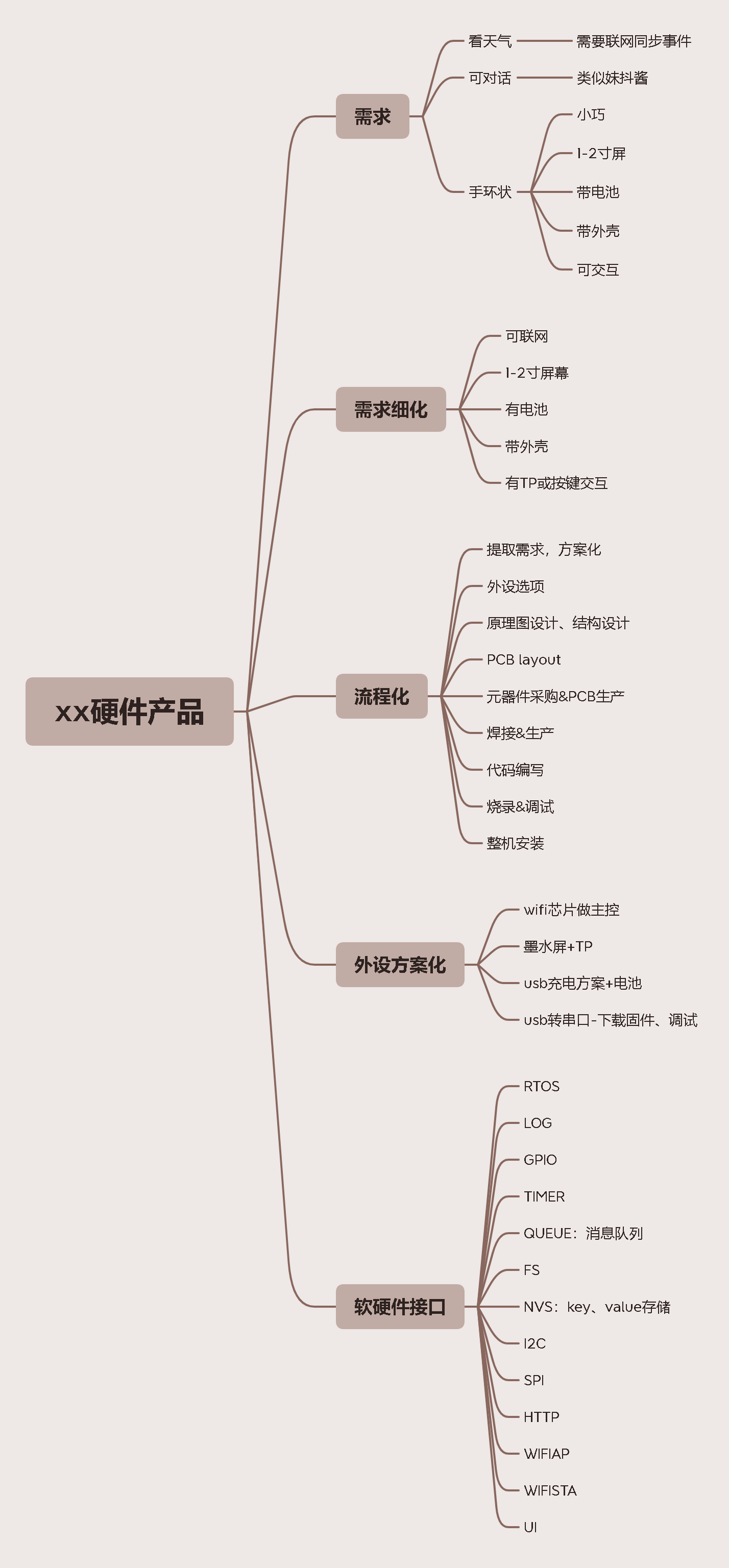
外设选型的网站:
- https://x.jlc.com/category/all
- https://www.52audio.com/archives/category/teardowns
- https://www.espressif.com/zh-hans/products/devkits
电商平台:
硬件部分
硬件基础知识


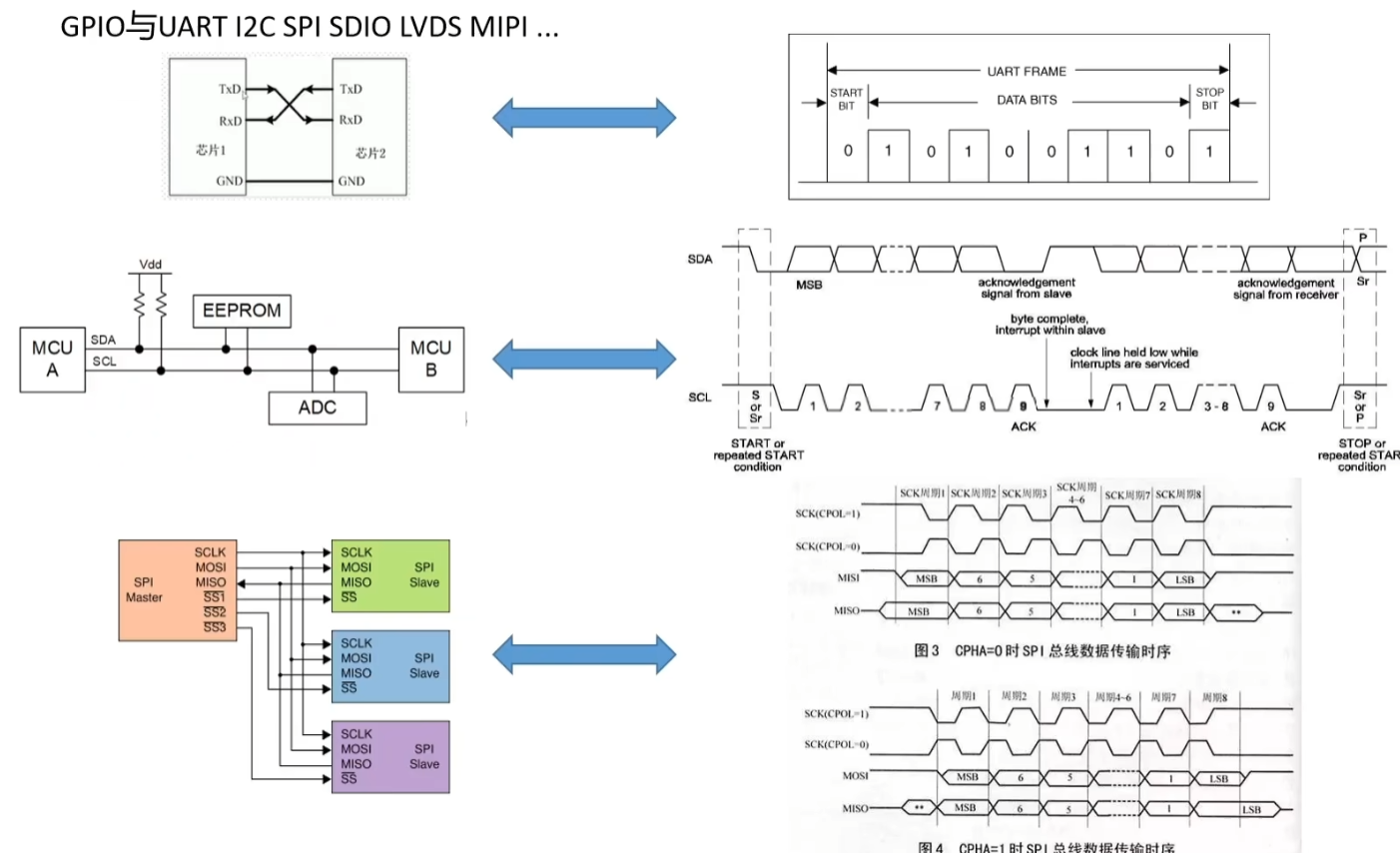
GPIO(通用输入输出)是一种数字信号引脚,可用于连接和控制外部设备。它可以被设置为输入或输出模式,用于读取传感器数据、控制执行器或与其他数字电路进行通信。
UART(通用异步收发传输器)是一种串行通信接口标准,用于在计算机和外部设备之间传输数据。它使用单个传输线进行全双工通信,常用于串口通信和调试。
I2C(Inter-Integrated Circuit)是一种串行通信协议,用于在集成电路芯片之间进行短距离的数据传输。它使用两根传输线(SDA 和 SCL)来实现多主从设备之间的通信,并支持多种设备连接。
SPI(Serial Peripheral Interface)是一种串行通信接口协议,用于在微控制器或其他数字设备之间传输数据。它使用四根传输线(MISO、MOSI、SCK 和 SS)来实现全双工通信,适用于高速数据传输和与外部设备的通信。
SDIO(Secure Digital Input/Output)是一种用于在计算机和外部设备之间传输数据的接口标准。它是基于SD卡的物理接口扩展,支持高速数据传输和多种设备连接。
LVDS(Low Voltage Differential Signaling)是一种低电压差分信号传输技术,用于在高速数据传输中减少电磁干扰和功耗。它通常用于显示器或其他需要高带宽和长距离传输的应用。
MIPI(Mobile Industry Processor Interface)是移动行业处理器接口的缩写,是一组用于移动设备的串行通信接口标准。它提供了多个通信协议,如MIPI CSI-2(摄像头接口)、MIPI DSI(显示接口)等。
这些接口和协议彼此独立,用于不同目的的数据传输和设备连接。它们可以在电子设备中同时或分别使用,根据具体的应用需求来选择适合的接口。例如,GPIO 可用于控制外部设备的输入和输出,而 UART、I2C、SPI 以及 SDIO 则用于与其他设备进行通信。LVDS 和 MIPI 则是用于高速数据传输和显示设备接口。

如何绘制原理图?
1、立创EDA工具
2、从外设选型记录的编号,把器件放入EDA
3、外设方案由Datasheet、TB、搜索确定
4、绘制原理图
立创商城:https://www.szlcsc.com/
立创EDA工具下载:https://lceda.cn/
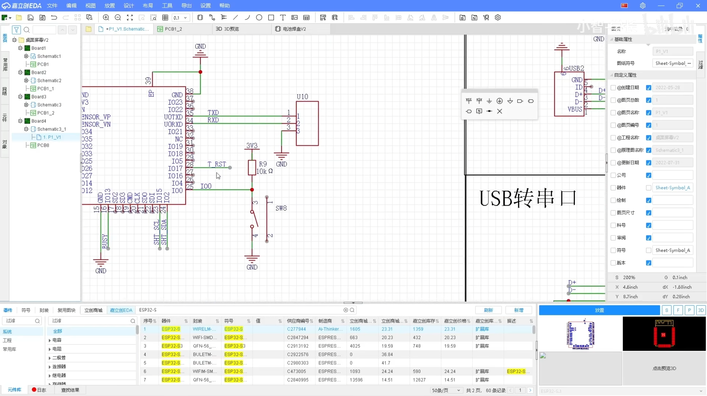
最小系统确定
ESP32WROOM32E数据手册
https://www.espressif.com.cn/zh-hans/products/modules
https://www.espressif.com.cn/sites/default/files/documentation/esp32-wroom-32e_esp32-wroom-32ue_datasheet_cn.pdf
外围设计原理图
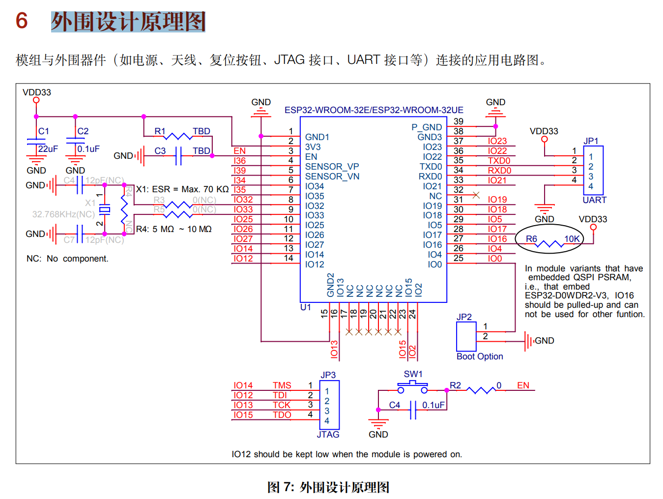
外设接口IO确定
查询数据手册,规划好哪些外设对应哪个IO口
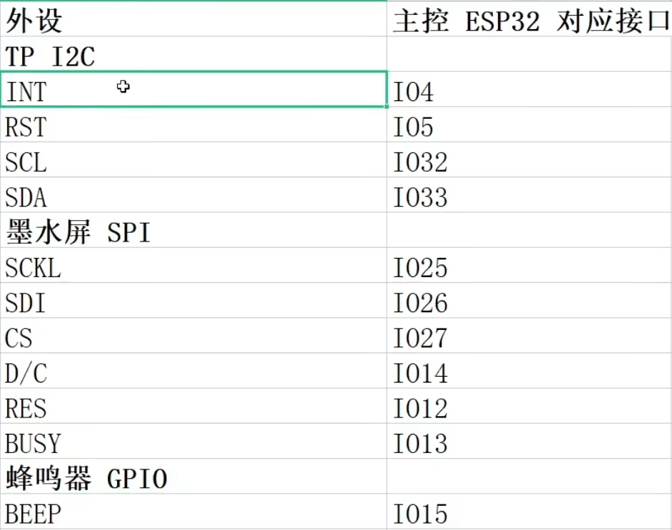
然后再EDA中绘制出来
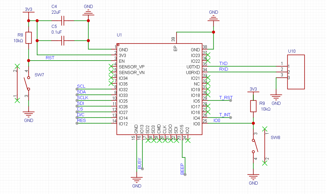
PCB Layout步骤
略,这里本人直接跳到软件部分,因为我已经有开发板了。
软件部分
开发环境搭建
1、安装虚拟机(vmware)
2、安装ubuntu,安装ssh samba
3、安装vscode
https://x509p6c8to.feishu.cn/docs/doccnk1gfc2Ddes4jzGDzm7L7tf(看环境搭建部分)
4、安装esp32开发依赖环境
ubuntu系统环境安装文档:https://x509p6c8to.feishu.cn/docx/doxcniDDyYcFo6BCkjUCnkO2aUb
windows系统环境安装文档:https://x509p6c8to.feishu.cn/docx/UnzmdlR0jocnZMxhXbAc2Fc5nBh
这里我用windows
运行hello world工程
安装后可以编译hello world工程测试,具体步骤:
将D:\Espressif\frameworks\esp-idf-v4.4.2\examples\get-started\hello_world目录拷贝到D:\Espressif\frameworks
打开ESP-IDF 4.4 PowerShell进入D:\Espressif\frameworks\hello_world目录下,输入命令:
idf.py set-target esp32s3
idf.py fullclean
idf.py build
idf.py -p COM5 flash monitor
其中esp32s3是我的单片机型号和com5是设备端口
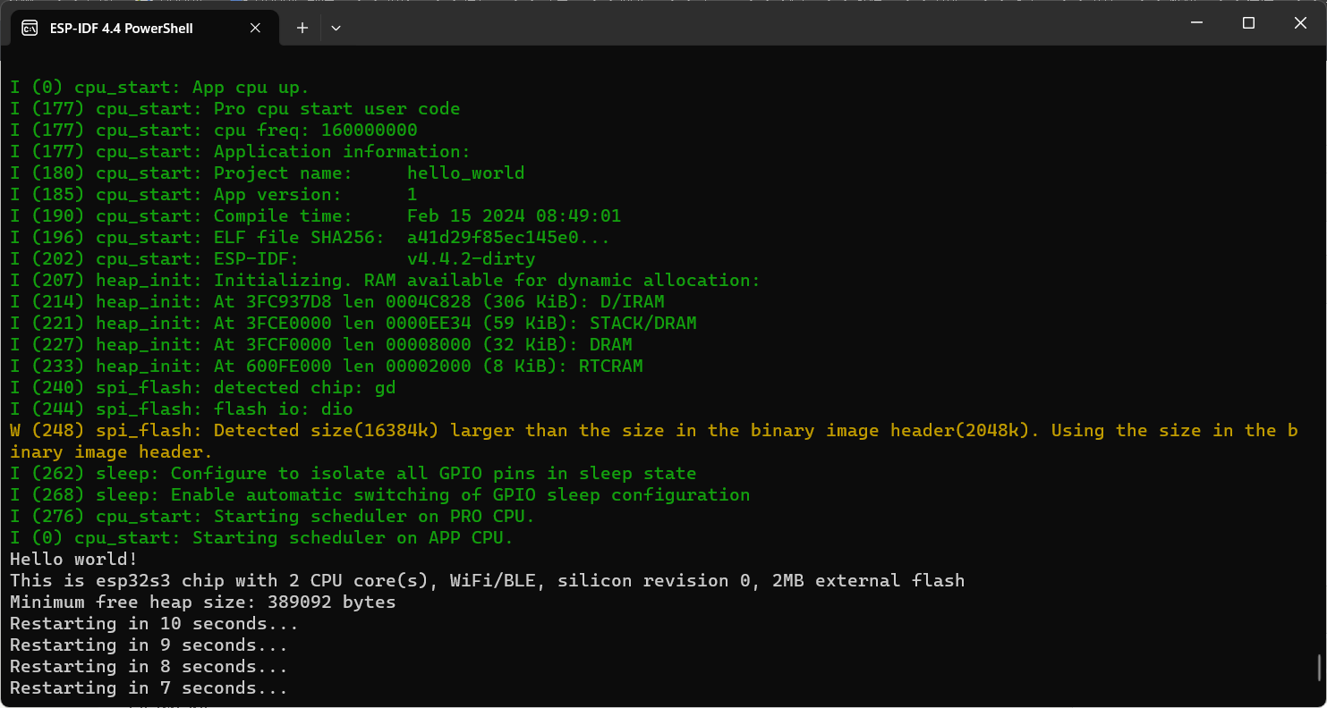
运行效果
退出的话按ctrl+]
git指令基础
sudo apt install git
git init
git add *
git commit -m "xxx"
git branch -l
git checkout -b dev
git tag -l
git tag -a v1.0 -m "xxx"
cmake和RTOS
CMake 是一个跨平台的开源构建工具,用于自动化管理软件构建过程。它可以生成与操作系统和编译器无关的构建脚本,使得项目更易于跨平台移植和构建。
实时操作系统(RTOS)是一种专门设计用于实时应用程序的操作系统。与通用操作系统相比,RTOS 更加注重响应性能、可预测性和实时性。RTOS 提供了实时任务调度、中断处理、资源管理和通信机制等功能,以满足实时应用程序对时间约束的要求。
在嵌入式领域,CMake 和 RTOS 通常结合使用来构建和部署实时应用程序。CMake 可以简化嵌入式项目的构建流程,并生成与特定 RTOS 兼容的构建脚本。RTOS 则为实时应用程序提供了必要的资源管理和调度功能,使开发者能够更方便地开发稳定、高效的嵌入式应用程序。
开发篇
日志打印程序
/* Hello World Example

   This example code is in the Public Domain (or CC0 licensed, at your option.)

   Unless required by applicable law or agreed to in writing, this
   software is distributed on an "AS IS" BASIS, WITHOUT WARRANTIES OR
   CONDITIONS OF ANY KIND, either express or implied.
*/
#include <stdio.h>
#include "sdkconfig.h"
#include "freertos/FreeRTOS.h"
#include "freertos/task.h"
#include "esp_system.h"
#include "esp_spi_flash.h"
#include "esp_log.h"

static const char *TAG = "MAIN APP";

void app_main(void)
{
    printf("Hello world!\n");

    /* Print chip information */
    esp_chip_info_t chip_info;
    esp_chip_info(&chip_info);
    printf("This is %s chip with %d CPU core(s), WiFi%s%s, ",
           CONFIG_IDF_TARGET,
           chip_info.cores,
           (chip_info.features & CHIP_FEATURE_BT) ? "/BT" : "",
           (chip_info.features & CHIP_FEATURE_BLE) ? "/BLE" : "");

    printf("silicon revision %d, ", chip_info.revision);

    printf("%dMB %s flash\n", spi_flash_get_chip_size() / (1024 * 1024),
           (chip_info.features & CHIP_FEATURE_EMB_FLASH) ? "embedded" : "external");

    printf("Minimum free heap size: %d bytes\n", esp_get_minimum_free_heap_size());

    ESP_LOGI(TAG, "system init V1.1");
    ESP_LOGW(TAG, "system init V1.1");
    ESP_LOGE(TAG, "system init V1.1");

    for (int i = 10; i >= 0; i--)
    {
        printf("Restarting in %d seconds...\n", i);
        vTaskDelay(1000 / portTICK_PERIOD_MS);
    }
    printf("Restarting now.\n");
    fflush(stdout);
    esp_restart();
}
任务创建
文档:https://docs.espressif.com/projects/esp-idf/zh_CN/release-v4.1/api-reference/system/freertos.html
/* Hello World Example

   This example code is in the Public Domain (or CC0 licensed, at your option.)

   Unless required by applicable law or agreed to in writing, this
   software is distributed on an "AS IS" BASIS, WITHOUT WARRANTIES OR
   CONDITIONS OF ANY KIND, either express or implied.
*/
#include <stdio.h>
#include "sdkconfig.h"
#include "freertos/FreeRTOS.h"
#include "freertos/task.h"
#include "esp_system.h"
#include "esp_spi_flash.h"
#include "esp_log.h"

static const char *TAG = "MAIN APP";

static void test_task_example(void *arg)
{
    for (;;)
    {
        vTaskDelay(1000 / portTICK_PERIOD_MS);
        printf("task run \n");
    }
}

void app_main(void)
{
    printf("Hello world!\n");

    /* Print chip information */
    esp_chip_info_t chip_info;
    esp_chip_info(&chip_info);
    printf("This is %s chip with %d CPU core(s), WiFi%s%s, ",
           CONFIG_IDF_TARGET,
           chip_info.cores,
           (chip_info.features & CHIP_FEATURE_BT) ? "/BT" : "",
           (chip_info.features & CHIP_FEATURE_BLE) ? "/BLE" : "");

    printf("silicon revision %d, ", chip_info.revision);

    printf("%dMB %s flash\n", spi_flash_get_chip_size() / (1024 * 1024),
           (chip_info.features & CHIP_FEATURE_EMB_FLASH) ? "embedded" : "external");

    printf("Minimum free heap size: %d bytes\n", esp_get_minimum_free_heap_size());

    ESP_LOGI(TAG, "system init V1.1");
    ESP_LOGW(TAG, "system init V1.1");
    ESP_LOGE(TAG, "system init V1.1");

    xTaskCreate(test_task_example, "test_task_example", 2048, NULL, 10, NULL);

    for (int i = 10; i >= 0; i--)
    {
        printf("Restarting in %d seconds...\n", i);
        vTaskDelay(1000 / portTICK_PERIOD_MS);
    }
    printf("Restarting now.\n");
    fflush(stdout);
    esp_restart();
}
DTimer&消息队列
文档:https://docs.espressif.com/projects/esp-idf/zh_CN/release-v4.1/api-reference/peripherals/timer.html
代码:
https://gitee.com/zhiyong21/desktop-screen-demo-d/tree/dev3/
/* Timer group-hardware timer example

   This example code is in the Public Domain (or CC0 licensed, at your option.)

   Unless required by applicable law or agreed to in writing, this
   software is distributed on an "AS IS" BASIS, WITHOUT WARRANTIES OR
   CONDITIONS OF ANY KIND, either express or implied.
*/
#include <stdio.h>
#include "esp_types.h"
#include "freertos/FreeRTOS.h"
#include "freertos/task.h"
#include "freertos/queue.h"
#include "driver/periph_ctrl.h"
#include "driver/timer.h"

#include "ds_timer.h"

#define TIMER_DIVIDER         16  //  Hardware timer clock divider
#define TIMER_SCALE           (TIMER_BASE_CLK / TIMER_DIVIDER/1000)  // convert counter value to ms seconds
#define TIMER_INTERVAL0_SEC   (10) // sample test interval for the first timer
#define TEST_WITH_RELOAD      1        // testing will be done with auto reload

/*
 * A sample structure to pass events
 * from the timer interrupt handler to the main program.
 */
typedef struct {
    uint64_t timer_minute_count;
    uint64_t timer_second_count;
} timer_event_t;

timer_event_t g_timer_event;

xQueueHandle timer_queue;

/*
 * Timer group0 ISR handler
 *
 * Note:
 * We don't call the timer API here because they are not declared with IRAM_ATTR.
 * If we're okay with the timer irq not being serviced while SPI flash cache is disabled,
 * we can allocate this interrupt without the ESP_INTR_FLAG_IRAM flag and use the normal API.
 */
void IRAM_ATTR timer_group0_isr(void *para)
{
    timer_spinlock_take(TIMER_GROUP_0);
    int timer_idx = (int) para;

    // /* Prepare basic event data
    //    that will be then sent back to the main program task */
    timer_event_t evt;

    timer_group_clr_intr_status_in_isr(TIMER_GROUP_0, TIMER_0);

    /* After the alarm has been triggered
      we need enable it again, so it is triggered the next time */
    timer_group_enable_alarm_in_isr(TIMER_GROUP_0, timer_idx);

    /* Now just send the event data back to the main program task */
    xQueueSendFromISR(timer_queue, &evt, NULL);
    timer_spinlock_give(TIMER_GROUP_0);
}

/*
 * Initialize selected timer of the timer group 0
 *
 * timer_idx - the timer number to initialize
 * auto_reload - should the timer auto reload on alarm?
 * timer_interval_sec - the interval of alarm to set
 */
static void example_tg0_timer_init(int timer_idx,
                                   bool auto_reload, double timer_interval_sec)
{
    /* Select and initialize basic parameters of the timer */
    timer_config_t config = {
        .divider = TIMER_DIVIDER,
        .counter_dir = TIMER_COUNT_UP,
        .counter_en = TIMER_PAUSE,
        .alarm_en = TIMER_ALARM_EN,
        .auto_reload = auto_reload,
    }; // default clock source is APB
    timer_init(TIMER_GROUP_0, timer_idx, &config);

    /* Timer's counter will initially start from value below.
       Also, if auto_reload is set, this value will be automatically reload on alarm */
    timer_set_counter_value(TIMER_GROUP_0, timer_idx, 0x00000000ULL);

    /* Configure the alarm value and the interrupt on alarm. */
    timer_set_alarm_value(TIMER_GROUP_0, timer_idx, timer_interval_sec * TIMER_SCALE);
    timer_enable_intr(TIMER_GROUP_0, timer_idx);
    timer_isr_register(TIMER_GROUP_0, timer_idx, timer_group0_isr,
                       (void *) timer_idx, ESP_INTR_FLAG_IRAM, NULL);

    timer_start(TIMER_GROUP_0, timer_idx);
}

/*
 * The main task of this example program
 */
static void timer_example_evt_task(void *arg)
{
    while (1) {
        timer_event_t evt;
        xQueueReceive(timer_queue, &evt, portMAX_DELAY);
        g_timer_event.timer_minute_count ++;
        //60s 计算一次 刷新时间
        if(g_timer_event.timer_minute_count >= 6000){
            g_timer_event.timer_minute_count = 0;
        }
        g_timer_event.timer_second_count ++;
        //1s计算一次
        if(g_timer_event.timer_second_count >= 100){
            g_timer_event.timer_second_count = 0;
        }
    }
}

/*
 * In this example, we will test hardware timer0 and timer1 of timer group0.
 */
void ds_timer_init(void)
{
    g_timer_event.timer_minute_count = 0;
    g_timer_event.timer_second_count = 0;
    timer_queue = xQueueCreate(10, sizeof(timer_event_t));
    example_tg0_timer_init(TIMER_0, TEST_WITH_RELOAD, TIMER_INTERVAL0_SEC);
    xTaskCreate(timer_example_evt_task, "timer_evt_task", 2048, NULL, 5, NULL);
}
未完待续